
Optimization of architectural design and construction with integrated BIM and PLM methodologies

Selection of the software platform
BIM and PLM systems typically employ different data formats and structures. Achieving seamless integration requires ensuring data interoperability between the two. This commonly involves developing data conversion tools or adopting widely accepted data exchange standards64. In the current international market, leading software vendors such as Autodesk, Bentley, Dassault Systèmes, Siemens, and Trimble, among others, have provided advanced solutions that support the integration of PLM and BIM. This directly mitigates the issue of data loss caused by transferring data through intermediate formats. Considering the diverse needs of digital projects in architectural design and construction, driven by the ongoing digital transformation in the construction industry, it is essential to prioritize aspects such as project management, design patterns, enterprise collaboration, digital delivery, and ecosystem development. The specific requirements are outlined in Tables 1 and 2, and 3.
Following a comprehensive comparison and evaluation of various software solutions on the basis of various requirements, this study ultimately selected the 3DEXPERIENCE foundational service platform by Dassault Systèmes. This choice not only addresses the comprehensive demands of the architectural industry’s digital transformation but also acknowledges the potential for secondary development on the 3DEXPERIENCE platform. This decision stems from a deep understanding of diverse requirements, aiming to deliver a more efficient, consistent, and innovative solution for digital architectural design and construction.
Platform configuration
In the process of integrating building information modeling (BIM) and product lifecycle management (PLM), meticulous consideration of platform configuration is crucial for ensuring system stability, efficient operation, and data security. The selection of software and hardware stands out as a key determinant for the successful implementation of seamless BIM–PLM integration.
Software configuration
The selection of software tailored to the specific requirements of architectural design and construction processes is crucial for successful integration. The chosen software should demonstrate compatibility, robust functionality, and the ability to support collaborative workflows across various stages of the project lifecycle. Therefore, we employed six key modules on the selected Dassault Systèmes 3DEXPERIENCE collaborative project work platform to meet these criteria.
-
ENOVIA: This module serves as a comprehensive project lifecycle management tool, facilitating efficient management of project data and processes from inception to completion. It enables collaborative planning, tracking, and execution of project tasks, ensuring seamless coordination among team members.
-
CATIA: CATIA is employed for professional modeling in various domains, including architecture, structure, HVAC, piping, electrical, and construction. Its robust 3D modeling capabilities allow for precise modeling, annotation, and delivery of design elements essential for architectural design and construction.
-
EXALEAD: EXALEAD is utilized for project data processing, enabling efficient organization, indexing, and retrieval of project-related information. It enhances data management and accessibility, facilitating informed decision-making throughout the project lifecycle.
-
3DEXCITE: This module is utilized for model rendering and visual representation, enhancing the visualization of design concepts and project outcomes. It enables stakeholders to gain insights into project designs and communicate ideas effectively.
-
DELMIA: DELMIA is employed for process and construction simulation, covering a wide range of activities from facade installation to final assembly. It enables simulation-based planning and optimization of construction processes, ensuring safety, efficiency, and quality in project execution.
-
SIMULIA: SIMULIA is utilized for numerical simulation, allowing for preconstruction experimentation and validation via digital twin models. It enables the consideration of factors such as the wind load in joint simulations, ensuring the accuracy and reliability of construction simulations.
The methodology employed in this study revolves around the utilization of a unified foundational collaboration platform, ensuring coherence among the major modules within the platform. This uniformity at the core data level facilitates seamless data exchange among the six modules, eliminating the need for manual data import and export processes. Consequently, this integrated approach significantly reduces the transfer of project data. The integration simplifies both the design and construction workflows, mitigates data silos, enhances interdisciplinary collaboration, and ultimately improves the overall efficiency and accuracy of the project. Furthermore, it ensures a cohesive digital environment, fostering effective project management.
Hardware configuration
The seamless integration of building information modeling (BIM) and product life cycle management (PLM) to support the digital transformation of the construction industry necessitates the careful selection of appropriate hardware configurations.
The wide adoption of cloud computing by enterprises for its myriad advantages is a necessary trend in the architectural industry65,66. By analyzing the characteristics of public, private, and hybrid cloud deployment models and considering the specific requirements of Central South Architectural Design Institute Co., Ltd., a decision was made to adopt a private cloud infrastructure. This choice was driven by considerations of security, compliance, customization needs, and greater control over data and performance.
To ensure seamless collaboration among design teams, multiple technologies were employed for high-speed data transfer and security. First, a dedicated network line was utilized, ensuring rapid transmission of design data between stakeholders and enhancing collaboration efficiency. Additionally, VPN technology provided a secure connection for remote users, allowing them secure remote access to the company’s design system from any location. The local area network within the company ensured reliable local connectivity, enabling internal staff to access the required resources swiftly and stably.
The design system, configured on this platform, diverges significantly from traditional design workflows by discarding the conventional file-based approach in favor of a database-driven cloud-based collaborative design methodology. In this system, design data are no longer stored in traditional folders and files but are unified in a robust database. An essential advantage of this method is the exceptionally high level of data correlation, allowing for more precise management of interdependencies among different design elements—a critical aspect for collaborative work on complex projects.
The storage of data in a database streamlines data management. Tasks such as backup, recovery, and maintenance become more straightforward, providing the company with enhanced data reliability and security. Furthermore, the real-time online collaborative features of this system offer significant convenience to the design team. Multiple stakeholders can simultaneously collaborate online, viewing and editing data in the database in real time, fostering high levels of teamwork and instant communication. This innovative approach not only enhances efficiency but also transforms the dynamics of collaborative work within the architectural design and construction domain.
Proposed integrated BIM and PLM management and business framework
To establish a robust foundation for integration, a platform-centric approach was adopted to delineate clear management and business processes, optimizing the organization and implementation of the project. The comprehensive project collaborative management workflow comprises the project planning process, platform data management process, project data management process, template validation process, dual-track design review process, and construction scheme design and review process. The personnel involved in the workflow span disciplines, companies, and regions and include project managers, PLM directors, discipline leaders, discipline chief designers, construction leaders, and platform administrators, among others. The project collaborative management and business framework is illustrated in Fig. 3a.

Proposed integrated BIM and PLM management and business framework. a Project management and overall business framework. b Template repository validation process. c Design model validation process. d Construction model validation process.
Project management personnel, guided by the outlined design and construction processes, formulated specific workflows:
-
Template Repository Validation Process: Managing template creation and repository entry involves discipline chief designers in template creation and validation by discipline leaders until approval, followed by repository entry and maintenance by the PLM director and platform administrator. Once approved, templates are accessible for further use by discipline leads. The processes are depicted in Fig. 3b.
-
Design Model Validation Process: Mandating reviews by discipline chief designers, discipline leads, and construction leads ensures that project design models transition downstream only after comprehensive validation. Joint approval by the PLM director and platform administrator precedes the final three-dimensional delivery. The processes are depicted in Fig. 3c.
-
Construction Model Validation Process: Initiated by construction leads, this process involves creating construction models on the basis of the design model. A review of the scheme by the PLM director, database maintenance by the platform administrator, and final organization of construction by the construction lead conclude the workflow. The processes are depicted in Fig. 3d.
At the initiation of the project, collaborative platform administrators create collaboration zones on the project collaborative management platform. Defining roles on the basis of the project members’ permissions, the team establishes project design and construction unit accounts and assigns licenses. Different accounts possess varying permissions on the basis of roles and job responsibilities.
During the planning phase, project managers, supported by collaborative platform administrators, create a project structure tree outlining the project’s logical progression from the conceptual design phase to the construction and maintenance phases. By utilizing the functionalities of the 3DEXPERIENCE platform, the team decomposes design and modeling tasks by functionality, clarifies input conditions, and defines the output. This process aids in task assignment, collaborative work, and project management. Each node in the project structure tree represents a work package, facilitating task breakdown, collaboration, and project management.
Throughout the project implementation, roles are assigned and managed according to workflows and designated work packages. This encompasses template library management, document management, and design tasks such as 3D model creation, 3D review, and 3D annotation. All the units and participants in the design and construction processes collaborate on the platform following the established collaborative workflows. This ensures streamlined communication, efficient collaboration, and adherence to the integrated project management and business framework.
Proposed integrated BIM and PLM workflow for architectural design and construction
Application of the integrated BIM and PLM collaborative platform
This project establishes a unified management and collaborative platform across disciplines, enterprises, and the entire workflow, leveraging a centralized data source. The platform supports seamless three-dimensional collaboration among professionals in architecture, structure, electromechanical systems, steel structures, geotechnics, curtain wall design, and construction. It facilitates real-time communication and collaboration between upstream and downstream enterprises via a shared model. The project’s implementation spans from the conceptual design phase to the construction phase, encompassing all aspects of site design, architectural design, structural design, electromechanical design, and construction. During the design phase, an evolutionary design approach based on components is employed. Specifically, the design progresses from LOD100 skeletal design to LOD200 component design, then to LOD300 product detailing, and finally to LOD400 fabrication model creation, where components refer to individual elements or parts of the building, such as walls, doors, windows, beams, columns, slabs, and reinforcements. As the levels advance, the model details become richer, the accuracy gradually improves, and the transmission of design parameters and information increases continuously. In the evolution from conceptual skeletal design to detailed design processes, details and accuracy are enhanced on the basis of the same model without the need for redundant modeling. This achieves cross-stage delivery on the basis of a single data source for the preliminary design, detailing, fabrication, construction, and operation phases, all of which are facilitated through cloud-based platforms. Both case study projects in this research achieve LOD400 models. The proposed integrated workflow is illustrated in Fig. 4.
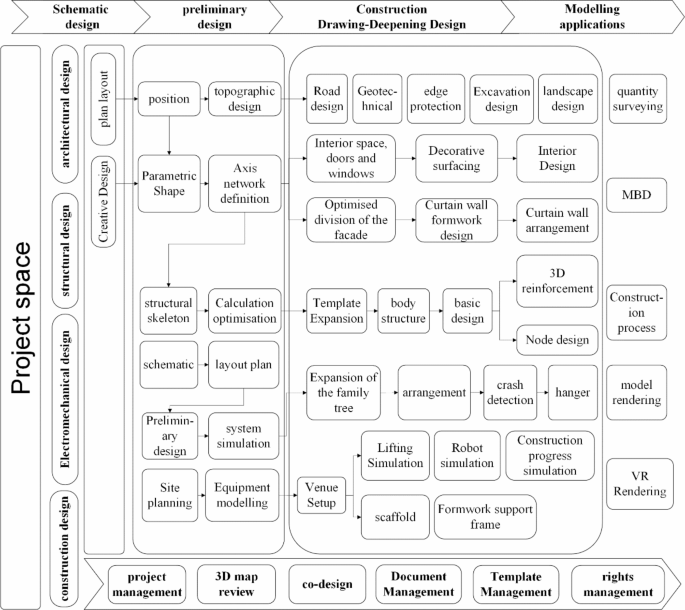
Proposed Integrated BIM and PLM Workflow for Architectural Design and Construction.
Case overview
Case one
The Wuhan Next-Generation Weather Radar Construction Project represents a pivotal collaboration between the China Meteorological Administration and the provincial government. It holds significance in Wuhan’s meteorological development, as outlined in the “13th Five-Year Plan for Wuhan Meteorological Development”, and is a pioneering project in the construction industry, spearheading digitized construction. Positioned atop Bafen Mountain in Jiangxia District, Wuhan, the project spans approximately 8672.01 m² of planned land, with a total construction area of 4230 m², comprising approximately 2693 m² above ground and 1537 m² below ground. With ground elevations ranging between 265.6 and 251.8, the structure comprises 26 above-ground floors and 1 basement level, standing at a height of 92.15 m. The project’s total investment is estimated at approximately 148 million RMB.
This endeavor faces multifaceted challenges, including complex structural design, intricate infrastructure layout, intricate construction arrangements, and exceedingly high construction difficulty.
-
Complex Structural Design: Adopting a reinforced concrete structure, the project features vertically inclined torsional components in twin towers, rendering the structure intricate. To meet operational requirements, the towers require a vibration period of less than 1 m. Additionally, the massive integrated radar room atop further complicates structural design and analysis, increasing the complexity.
-
Intricate Infrastructure Layout: Constrained indoor space results in significant clashes between disciplines, especially in the intricate layout of infrastructure.
-
Challenges in Construction Arrangement: Located at the summit of Bafen Mountain in Jiangxia District, Wuhan, site constraints pose challenges in arranging tower cranes, external scaffolding, internal formwork, and construction platforms.
-
Exceedingly High Construction Difficulty: The irregular concrete structure presents numerous difficulties in positioning, processing structural templates, and installing curtain wall panels, contributing to exceptionally high construction complexity.
Despite these daunting challenges, this project notably achieved China’s first-ever PLM–BIM integration in architectural engineering, setting a precedent as the country’s pioneer seamless digital construction project. It stands as a benchmark in the industry, marking a milestone in low-carbon, environmentally friendly digital construction.
Collaborative design
The typical applications and achievements of BIM–PLM integration in the design phase include the following aspects:
-
(1)
Site Design: Project terrain, road, and landscape models are created on the collaborative platform. The site layout is optimized on the basis of detailed terrain models, which included foundation designs for the main piles and retaining walls. The platform facilitates excavation, backfilling on the basis of the geological layer distribution, and design of the pile foundation lengths.
-
(2)
Design: CATIA’s parametric design capabilities are utilized within the platform to adjust architectural surface rotation angles continuously, optimizing building forms. The optimal rotation angle was determined to be 18° through iterative adjustments. Refer to Fig. 5a.
-
(3)
Curtain Wall Reconstruction and Optimization: Reconstruction of freeform surfaces via regularized generation logic employs intelligent optimization algorithms to iteratively compute the surfaces closest to the original surfaces. This process ensured more uniform and standardized panel specifications after division.
-
(4)
Structural Selection: Parametric design tools are utilized on the platform to swiftly create structural skeleton lines on the basis of architectural outlines. Multiple generation logics are developed according to various system characteristics, enabling the creation of structural calculation models. These models are interactively linked with structural analysis software for comparative assessments, addressing complexities in modeling complex structures; refer to Fig. 5b.
-
(5)
Structural Design: Based on the comparative results, structural design of components, including beams, columns, slabs, and foundations, as well as detailed concrete and steel structure designs, is carried out on the collaborative platform. The concrete structure details include the reinforcement layout, the bending and anchoring of the steel bars, and the node reinforcement design. The detailing of the steel structure includes component selection, node design, and finite element simulations; refer to Fig. 5c.
-
(6)
Electromechanical design: This includes schematic design, pipeline layout, comprehensive pipeline integration, and system simulations. The electromechanical schematic design is developed on the basis of architectural and functional requirements. The platform facilitates comprehensive design for plumbing, HVAC, and electrical systems, identifying and resolving clashes with other disciplines; refer to Fig. 5d.
-
(7)
Numerical Simulation: An integrated numerical simulation system is used to analyze and evaluate a building’s response under various physical conditions. This includes the design and validation of HVAC, fire safety, and electrical systems, contributing to the technical support for the entire lifecycle management of the building; refer to Fig. 5e.
-
(8)
Large-Scale Precise Modeling: Large-scale, precise models encompassing both architectural and construction process models are established.
-
(9)
Engineering calculation: Detailed models are utilized to accurately estimate the material requirements for concrete, steel, and construction measures such as scaffolding and formwork on the basis of the project’s construction process. The 3D models facilitate precise cost control. Refer to Fig. 5f.

Typical applications and achievements of BIM–PLM integration in the case one design phase. a Form design. b Structural selection. c Structural design. d Electromechanical design. e Numerical simulation. f Engineering calculation. This figure was drawn and edited by the authors of this paper, Shen Zhang, Yuchen Tang, and Hao Yang, via 3DEXPERIENCE, version 2022X (https://www.3ds.com/3dexperience).
Collaborative construction
On the basis of a unified platform, construction design personnel integrated BIM–PLM applications into the construction phase, encompassing construction scheme development, construction disclosures, virtual design, and construction. Typical applications in this study included the following:
-
(1)
On-Site Tower Crane Positioning: The double-curved surface design made it difficult to determine the optimal position of the tower crane via traditional 2D drawings. By collaborating with the construction project manager, the tower crane and adjacent wall positions were accurately designed on the basis of the 3D model. The figure shows the exact parameters used to define wall lengths and angles, which were derived from the model. Refer to Fig. 6a.
-
(2)
Scaffolding Design: Determining scaffolding schemes for complex curved surfaces was equally challenging when 2D plans were used. The scaffolding plan was established through a precise 3D layout with the scaffolding structures highlighted to indicate their placement in relation to the main structure and tower crane. Refer to Fig. 6b.
-
(3)
Formwork Design and Validation: The formwork scheme was developed through collaboration and verified through simulation analysis. Figure 6c illustrates both the model-based formwork layout and the corresponding simulation results, which validated the material selection and structural stability. Refer to Fig. 6c.
-
(4)
Construction Unloading Platform Design: Fig. 6d displays the 3D layout and final construction plan for the unloading platform. The design process, which is complicated by the building’s shape, required coordination between 3D modeling and site communication to resolve form and installation issues. Refer to Fig. 6d.
-
(5)
Complex Reinforcement Detailing: Due to the intricate arrangement of steel bars at various nodes, Fig. 6e focuses on enlarged views of critical connection nodes. These visualizations provide construction workers with a comprehensive understanding of how to implement precise steel bar layouts at key intersections. Refer to Fig. 6e.
-
(6)
Concrete Pouring Formwork Scheme: Collaborative efforts were made with the construction unit to combine the model to finalize the tower structure construction plan. The curved surfaces from the design model were unfolded to obtain intersection lines. These lines were then printed on paper by 3D printing, cut, pasted onto template materials, cut again, and finally installed as formwork.
-
(7)
Lifting Simulation: Following the establishment of tower crane positioning, scaffolding, and formwork schemes, lifting simulations were conducted.
-
(8)
Construction Simulation: Fig. 6f illustrates how 3D model-based simulations were used to develop construction operation manuals and training videos for onsite workers. The simulation ensured construction precision and enhanced workflow efficiency. Comparison between 3D simulations and real-life site photography provides a clear indication of the alignment between planned and actual construction. Refer to Fig. 6f.

Typical applications and achievements of BIM–PLM integration in the case one construction phase. a On-site tower crane positioning. b Scaffolding design. c Formwork design and validation. d Construction unloading platform design. e Complex reinforcement detailing. f Construction simulation. This figure was drawn and edited by the authors of this paper, Shen Zhang, Yuchen Tang, and Hao Yang, via 3DEXPERIENCE, version 2022X (https://www.3ds.com/3dexperience).
Case two
The Hubei Center for Disease Control and Prevention (CDC) Comprehensive Capacity Enhancement Project (Phase I) is a key initiative within the public health system of Hubei Province. To address the specific needs of Hubei Province, this project sought to establish a model for the province, fundamentally improving the existing framework for responding to infectious diseases and other public health emergencies. Located on Zhuodaoquan North Road in the Hongshan District of Wuhan, the project encompasses a total floor area of 79,666.7 square meters, including nine above-ground floors and two underground levels. The project faced several challenges, including the construction of large-span steel structures, a tight schedule, and limited site space. The integration of BIM and PLM methodologies effectively addressed these challenges.
Collaborative design
-
(1)
Three-Dimensional Geological Modeling: This allowed for a more objective and vivid description of geological features, overcoming the limitations of using 2D drawings to describe 3D geological features. It enabled excavation, backfilling, and pile foundation length design on the basis of the distribution of geological layers. Refer to Fig. 7a.
-
(2)
Curtain Wall Optimization and Design: By optimizing and segmenting the facade, freeform surfaces were reconstructed to make the divided panel specifications more uniform and consistent. The curtain wall unit design was based on segmented surfaces and considered embedded positioning during the design phase to guide onsite construction. Refer to Fig. 7b.
-
(3)
Structural Design: A proprietary interface program was developed between 3DE and SAP2000 software, which converts 3DE building skeleton lines into beam, column, and wall units. It then invokes SAP2000 to generate analytical models for structural analysis. Refer to Fig. 7c.
-
(4)
Structural Deepening: Combining structural analysis results, concrete and steel structure node finite element simulations were conducted via CATIA’s basic design and SIMULIA numerical simulation functions. Refer to Fig. 7d.
-
(5)
Mechanical and Electrical Design: Integrated architectural and structural design schemes, including equipment selection schematic design, pipeline layout, comprehensive pipeline integration, and system simulation, were used to carry out mechanical and electrical professional design. Refer to Fig. 7e.
-
(6)
3D Review: In a three-dimensional digital environment for review, modification, feedback, and confirmation of designs, deepening models, construction measures, and construction plans were utilized to achieve refined management of the design process, effectively controlling design quality and ensuring traceability of the design results. Refer to Fig. 7f.

Typical applications and achievements of BIM–PLM integration in the case two design phase. a Three-dimensional geological modeling. b Optimization of curtain wall separation for the whole project. c 3DE and SAP2000 interface programs. d Typical type of reinforced concrete joint. e Electromechanical three-dimensional full model. f Three-dimensional proofreading. This figure was drawn and edited by the authors of this paper, Shen Zhang, Yuchen Tang, and Hao Yang, via 3DEXPERIENCE, version 2022X (https://www.3ds.com/3dexperience).
Collaborative construction
-
(1)
Overall Scheme Formulation and Verification: Through preliminary simulation planning of project office areas, living areas, and construction sites, the application of 3D scene layouts at construction sites were simulated to comprehensively and accurately grasp the layout of construction site plans, improve the utilization rate of construction site space, and avoid secondary handling.
-
(2)
Excavation Support Removal Simulation: The actual situation onsite was restored via a model combined with numerical simulation analysis technology to determine the arrangement of excavation support removal schemes, ensuring the feasibility of construction measures. Refer to Fig. 8a.
-
(3)
High- and Large-Template Support System Design: On the basis of the design model, the construction unit created a high- and large-template support frame model on the same platform to determine whether the construction support frame scheme was reasonable, providing a theoretical basis for onsite material selection. Refer to Fig. 8b.
-
(4)
Steel Structure Installation Simulation: The entire process of steel structure installation in virtual space was simulated to discover difficulties in the construction process in advance, rehearse schemes, and improve construction safety and efficiency. A real-time comparison between the construction status and the model was conducted to promptly correct deviations and ensure construction accuracy. Refer to Fig. 8c.
-
(5)
Curtain Wall Installation Simulation: Based on the curtain wall construction scheme, typical floor curtain wall installation construction simulation videos were produced through the platform’s construction simulation module, facilitating onsite explanations of construction schemes to construction personnel.
-
(6)
Mechanical and Electrical Installation Simulation: On the basis of the overall linkage lifting installation scheme of mechanical and electrical pipelines, typical mechanical and electrical installation area construction simulation videos were produced through the platform’s construction simulation module, facilitating onsite explanations of construction schemes to construction personnel. Refer to Fig. 8d.
-
(7)
Three-Dimensional Annotation: The intuitive, visual, and accurate expression features of the three-dimensional model were fully utilized to eliminate potential risks of inconsistency between 3D and 2D drawings through 3D annotations, reducing downstream personnel’s (processing, manufacturing, construction, operation and maintenance, etc.) understanding time and errors in the model. Refer to Fig. 8e.
-
(8)
Three-Dimensional Delivery: On the basis of 3D annotations, a steel structure installation guide manual was prepared. The manual details the component partitioning, component positioning, component coding, construction sequence, precautions, and personnel, material, machinery, and material information for steel structure installation, making construction tasks clearer. The components here refer to the various parts and elements of the steel structure, such as beams, columns, connections, braces, and other structural elements. Refer to Fig. 8f.
-
(9)
Three-Dimensional Disclosures: Completed technical disclosures were expressed using a three-dimensional digital model instead of drawings, presenting detailed structures in a more intuitive manner.

Typical applications and achievements of BIM–PLM integration in the case two construction phase. a Interior support construction. b Independent research and development of scaffolding and formwork design tools. c Simulation of the installation of steel structures on typical floors. d Electromechanical installation simulation. e Floor steel column specifications and positioning marking. f, Three-dimensional disclosure. This figure was drawn and edited by the authors of this paper, Shen Zhang, Yuchen Tang, and Hao Yang, via 3DEXPERIENCE, version 2022X (https://www.3ds.com/3dexperience).
Comprehensive assessment of the integrated BIM and PLM approach
Establishment of assessment criteria and indicators
In this study, focus group discussions and semistructured interviews were employed to identify current issues in the traditional project design and construction phases, as well as stakeholders’ concerns. These insights were used to establish assessment criteria and their respective indicators, which were then applied to projects integrating BIM and PLM to comprehensively evaluate their effectiveness.
-
(1)
Sample Selection: Key stakeholders closely associated with both traditional projects and those using the integrated BIM–PLM approach were selected as the study sample. These stakeholders included owners, investors, design firms, project team members, and government authorities for the design phase, as well as construction firms, project team members, material suppliers, supervisory units, researchers, and subcontractors for the construction phase (as shown in Fig. 9). The total sample size was 45 participants, covering various disciplines, enterprises, and regions to ensure comprehensiveness and representativeness.
-
(2)
Focus Group Discussions: Five focus group discussions were organized, each comprising 8–10 participants. Guided by the researchers, these discussions utilized open-ended questions to delve into the current issues and concerns in traditional projects. Each session lasted approximately 1.5 h and was recorded for analysis. Five key assessment criteria were established from these discussions, as detailed in Table 4.
-
(3)
Semistructured Interviews: Following the focus group discussions, the researchers conducted semistructured interviews with each participant. The interview questions were based on the five assessment criteria identified in the focus groups and covered the establishment of indicators, overall project effectiveness evaluation, and recommendations for future project implementations. The questions were tailored according to each interviewee’s role and background. Each interview lasted 30–45 min and was recorded for analysis. The evaluation of project effectiveness and recommendations for future implementations are discussed in the Results and Discussion sections and will not be reiterated here. The specific indicators established for the assessment criteria are as follows:
-
Cross Collaboration (fraction/days): information sharing rate, problem-solving time, and cross-department task completion rate.
-
Quality (points): deepening concrete structures, deepening steel structures, 3D proofreading; steel structure installation, and total level program.
-
Duration (weeks): curtain wall optimization and design, concrete structure deepening construction, steel structure deepening construction, pipe optimization and comprehensive arrangement, component processing, general flat plan construction, 3D delivery, and project construction management.
-
Cost (million RMB): curtain wall, site use, labor, construction machinery and tools, steel structure, autoclaved lightweight concrete panel, other direct costs, and other indirect costs.
-
Waste (fraction): material waste, rework, nonproductive time, and energy consumption.
-
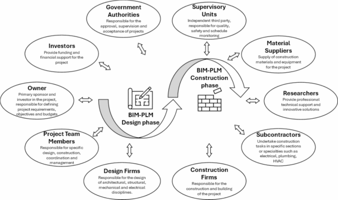
Stakeholders of the BIM–PLM integration project.
All methods were carried out in accordance with relevant guidelines and regulations. All experimental protocols were approved by the Academic Committee of Hubei University of Technology. Informed consent was obtained from all the subjects and/or their legal guardian(s) prior to their participation in the study.
Establishment of objective functions and constraints
In this subsection, the optimization results of the BIM–PLM project are evaluated on the basis of the objective function67. The project’s degree of collaboration, quality score, total duration, cost, and waste are considered in the objective function, with the optimal solutions for the objective function variables corresponding to the optimal values of the variables: highest collaboration, highest quality score, shortest total duration, lowest cost, and minimal waste. A mathematical model for the objective function was established:
$$F=7+S+Q – (T+C+W)$$
(1)
In the formula, S is the cross-collaboration, Q is the quality score, C is the cost quantity, T is the total duration of the project, and W is the waste. The values of the subindicators of their respective variables are analyzed and normalized, and their values are restricted to between 0 and 1 to equalize the degree of influence of each indicator on the total indicator. The constant 7 serves as a baseline adjustment value to adjust the range of the final result to ensure that the value of F is not too low or negative because of the negative effects of other variables.
(1) Cross-collaboration
$$S=\sum\nolimits_{{i=1}}^{n} {\frac{{{S_i} – {S_{\hbox{min} }}}}{{{S_{\hbox{max} }} – {S_{\hbox{min} }}}}} +\sum\nolimits_{{i=1}}^{m} {\frac{{{S_{\hbox{max} }} – {S_i}}}{{{S_{\hbox{max} }} – {S_{\hbox{min} }}}}}$$
(2)
where \({S_i}\) is the collaboration indicator for the i-th item, \({S_{\hbox{min} }}\) is the minimum value of the collaboration indicators for each subitem, and \({S_{\hbox{max} }}\) is the maximum value of the collaboration indicators for each subitem. In the context of specific projects, n is assigned a value of 2 (set to positive correlation), and m is assigned a value of 1 (set to negative correlation). The subprojects are the information sharing rate, problem-solving time (negative correlation), and cross-department task completion rate.
(2) Quality
$$Q=\sum\nolimits_{{i=1}}^{n} {\frac{{{Q_i} – {Q_{\hbox{min} }}}}{{{Q_{\hbox{max} }} – {Q_{\hbox{min} }}}}}$$
(3)
In the formula, \({Q}_{i}\) is the quality indicator value for the i-th item, \({Q}_{min}\) is the minimum value of the quality indicators for each subitem, and \({Q}_{max}\) is the maximum value of the quality indicators for each subitem. Based on the specific project situation, n is assigned a value of 5. The subprojects are deepening concrete structures, deepening steel structures, 3D proofreading, steel structure installation, and the total level program.
(3) Duration
$$\left\{ \begin{gathered} T=\sum\nolimits_{{i=1}}^{n} {\frac{{{T_i} – {T_{\hbox{min} }}}}{{{T_{\hbox{max} }} – {T_{\hbox{min} }}}}} \hfill \\ 0 \leqslant {T_i} \leqslant {T_{total}} \hfill \\ \sum\nolimits_{{i=1}}^{n} {{T_i} \leqslant {T_{total}}} \hfill \\ \end{gathered} \right.$$
(4)
where \({T}_{i}\) is the duration indicator value of the i-th item, \({T}_{min}\) is the minimum value of the duration indicators for each subitem, \({T}_{max}\) is the maximum value of the duration indicators for each subitem, and \({T}_{total}\) is the total duration limit, which represents the maximum value of the total duration of the project. On the basis of the specific project situation, n is assigned a value of 8. The subprojects include curtain wall optimization and design, concrete structure deepening construction, steel structure deepening construction, pipe optimization and comprehensive arrangement, component processing, general flat plan construction, 3D delivery, and project construction management.
(4) Cost
$$C={\sum\nolimits_{{i=1}}^{n} {\frac{{{C_i} – {C_{\hbox{min} }}}}{{{C_{\hbox{max} }} – {C_{\hbox{min} }}}}} _i}$$
(5)
Similarly, in the formula, \({C}_{i}\) is the cost indicator for the i-th item, \({C}_{min}\) is the minimum value of the cost indicators for each subitem, and \({C}_{max}\) is the maximum value of the cost indicators for each subitem. On the basis of the specific project situation, an n value of 8 is assigned. The subprojects include curtain walls, site use, labor, construction machinery and tools, steel structures, autoclaved lightweight concrete panels, other direct costs, and other indirect costs.
(5) Waste
$$W=\sum\nolimits_{{i=1}}^{n} {\frac{{{W_i} – {W_{\hbox{min} }}}}{{{W_{\hbox{max} }} – {W_{\hbox{min} }}}}}$$
(6)
In the formula, \({W_i}\) is the index value of the level of waste for the ith subitem, \({W_{\hbox{min} }}\) is the minimum value of the waste index for each subitem, and \({W_{\hbox{max} }}\) is the maximum value of the waste index for each subitem. According to the specific project, n is assigned a value of 4. The subitems are material waste, rework, nonproductive time, and energy consumption.
Furthermore, in terms of design variable constraints and design standard constraints, the relevant indicators of BIM–PLM projects should also meet the requirements of the owner, actual project conditions, quality and safety standards, and environmental regulations, which will not be repeated here. Next, the final quality score, duration, and cost are calculated based on the specific workload of each subproject and the quality, duration, and cost indicators for each sub project. Finally, based on Formulas 1–4, Q, T, and C of the project are calculated and substituted into the objective function formula, and finally, the comparison results of the objective function between the traditional project and the BIM–PLM project are obtained.
link


